
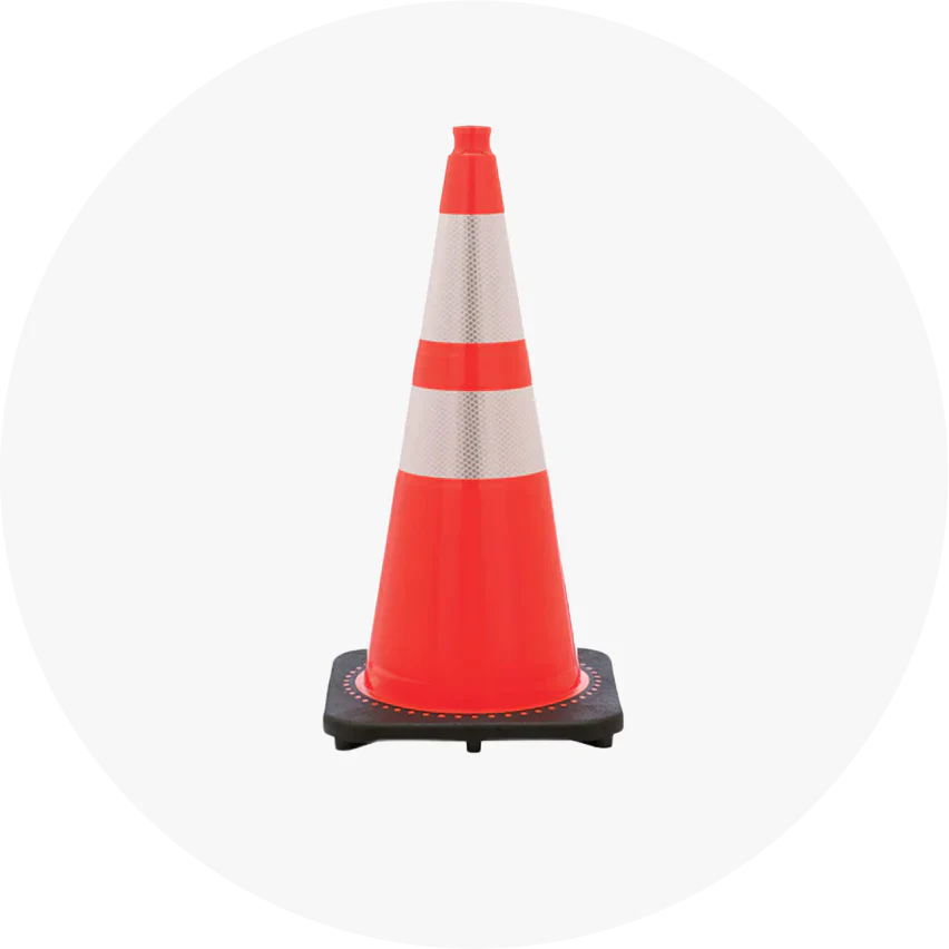






Traffic cones in a lane closure taper should generally be spaced no farther apart in feet than the roadway speed in mph, while cones along straight sections should be spaced no farther than twice that distance. Taper length depends on traffic speed and the width of the lane being closed.
The MUTCD provides two formulas:
-
40 mph or less: L=WS2/60
-
45 mph or more: L=WS
Here, L is taper length in feet, W is the lateral offset in feet, and S is the selected roadway speed in mph.
These formulas are guidance for designing temporary traffic control layouts. Actual installations must follow the approved traffic control plan and applicable state DOT requirements.
How Far Apart Should Traffic Cones Be?
Cone spacing depends on whether the devices form a taper or guide vehicles along a straight section of roadway.
Under MUTCD Section 6K.01, the recommended maximum spacing for channelizing devices is based on the posted speed limit.
|
Road speed |
Maximum taper spacing |
Maximum tangent spacing |
|
25 mph |
25 feet |
50 feet |
|
30 mph |
30 feet |
60 feet |
|
35 mph |
35 feet |
70 feet |
|
40 mph |
40 feet |
80 feet |
|
45 mph |
45 feet |
90 feet |
|
50 mph |
50 feet |
100 feet |
|
55 mph |
55 feet |
110 feet |
|
60 mph |
60 feet |
120 feet |
|
65 mph |
65 feet |
130 feet |
|
70 mph |
70 feet |
140 feet |
These values represent recommended maximums, not required minimum spacing. Closer placement may be necessary around curves, intersections, or visually complex work zones.
For roadway applications, the selected Traffic cones must also meet applicable height, color, and nighttime visibility requirements.
What Are the Main Parts of a Lane Closure?
A temporary lane closure consists of separate traffic control areas that warn approaching drivers, move vehicles into an available lane, and protect the work operation.
Typical lane closure sequence
1
Advance warning area
Signs alert approaching drivers
2
Transition area
Cones form the merging taper
3
Buffer space
Clear separation before the work area
4
Activity area
Work space and adjacent traffic space
5
Termination area
Drivers return to their normal path
Conceptual sequence only. Not a traffic control installation drawing.
Advance warning signs provide drivers with information before they reach the taper.
The transition area guides traffic out of the closed lane. The buffer space separates approaching traffic from the activity area and should remain clear.
What Are the Different Types of Lane Closure Tapers?
The MUTCD identifies several taper configurations according to how traffic is redirected.
|
Taper type |
Recommended length |
Purpose |
|
Merging |
At least L |
Combines traffic into another lane |
|
Shifting |
At least 0.5L |
Moves traffic laterally |
|
Shoulder |
At least 0.33L |
Closes or restricts a shoulder |
|
One-lane, two-way |
50–100 feet |
Guides alternating traffic through one lane |
|
Downstream |
50–100 feet |
Guides traffic back toward the normal path |
The two shorter taper types generally use channelizing devices at approximately 20-foot intervals.
A merging taper requires greater length because drivers must enter an adjacent traffic stream.
These criteria appear in MUTCD Table 6B-3.
How Do You Calculate Traffic Cone Taper Length?
Calculate taper length by determining roadway speed, measuring the lateral offset, and applying the appropriate MUTCD formula.
For speeds of 40 mph or less:
L=WS260
For speeds of 45 mph or more:
L=WS
Example 1: 30 mph Road With an 11-Foot Lane
L=1130260=165feet
The calculated merging taper length is 165 feet.
At a maximum spacing of 30 feet, seven cones provide six intervals of 27.5 feet, including devices at both ends.
Example 2: 45 mph Road With a 12-Foot Lane
L=1245=540feet
The calculated merging taper length is 540 feet.
At 45-foot spacing, the taper contains 12 intervals and requires 13 cones, including both endpoints.
The formula changes between the 40 mph and 45 mph speed categories. Do not interchange the equations.
Lane Closure Taper Length Chart
For a 12-foot lateral offset, the following values are calculated from MUTCD Table 6B-4.
|
Speed |
Merging taper |
Shifting taper |
Shoulder taper |
|
25 mph |
125 ft |
62.5 ft |
41.3 ft |
|
30 mph |
180 ft |
90 ft |
59.4 ft |
|
35 mph |
245 ft |
122.5 ft |
80.9 ft |
|
40 mph |
320 ft |
160 ft |
105.6 ft |
|
45 mph |
540 ft |
270 ft |
178.2 ft |
|
50 mph |
600 ft |
300 ft |
198 ft |
|
55 mph |
660 ft |
330 ft |
217.8 ft |
|
60 mph |
720 ft |
360 ft |
237.6 ft |
|
65 mph |
780 ft |
390 ft |
257.4 ft |
|
70 mph |
840 ft |
420 ft |
277.2 ft |
Shoulder taper values use the table's 0.33 multiplier. Actual layouts may require adjustments based on roadway geometry and engineering judgment.
How Many Traffic Cones Are Needed for a Lane Closure?
Cone quantity depends on taper length, device spacing, buffer length, work-zone length, and downstream taper requirements.
For a single continuous taper:
\[ N=\left\lceil\frac{L}{D}\right\rceil+1 \]
Where N is the estimated number of cones, L is taper length, and D is the chosen maximum spacing.
|
Example |
30 mph roadway |
45 mph roadway |
|
Lane width |
11 ft |
12 ft |
|
Merging taper |
165 ft |
540 ft |
|
Cone spacing |
Up to 30 ft |
Up to 45 ft |
|
Estimated taper cones |
7 |
13 |
These counts cover the merging taper only. Additional devices are needed along the activity area, at the downstream taper, and wherever the approved plan specifies them.
What Are Buffer Spaces and Advance Warning Areas?
A longitudinal buffer space separates approaching traffic from the work space. It provides additional distance between the transition and the location where workers or equipment operate.
MUTCD Table 6B-2 provides stopping sight distances used in evaluating longitudinal buffer space.
|
Road speed |
Stopping sight distance |
|
30 mph |
200 ft |
|
40 mph |
305 ft |
|
45 mph |
360 ft |
|
55 mph |
495 ft |
|
65 mph |
645 ft |
|
70 mph |
730 ft |
No work activity, vehicles, or stored materials should occupy the designated buffer space.
Advance warning sign placement also depends on roadway classification, speed, and the approved traffic control plan.
When Should Traffic Cones Be Spaced Closer Together?
Closer spacing can improve guidance where the roadway environment makes the intended travel path difficult to recognize.
Examples include curves, intersections, driveways, nighttime operations, and visually complex construction areas.
However, longer tapers are not automatically safer. MUTCD Section 6B.08 notes that excessively long tapers can encourage delayed lane changes, especially on urban roads with frequent access points.
How Should Crews Set Up and Remove Lane Closure Cones?
Lane closure installation and removal expose workers to moving traffic.
The work sequence should follow the approved temporary traffic control plan and the responsible agency's procedures.
Before beginning, crews should confirm the placement sequence, advance warning devices, work vehicles, communications, and required protective equipment.
Shadow vehicles and truck-mounted attenuators may be required for certain operations.
Workers should not improvise cone placement from an unprotected live traffic lane.
During removal, maintain the required traffic control protection until workers and equipment have cleared the affected area.
What Are the Most Common Cone Placement Mistakes?
Common problems include:
-
Confusing cone spacing with total taper length.
-
Applying the wrong taper formula.
-
Forgetting the final cone when calculating intervals.
-
Leaving equipment inside buffer spaces.
-
Using the same spacing for every roadway.
-
Assuming longer tapers always improve traffic flow.
-
Omitting required signs or other traffic control devices.
These errors can produce layouts that differ significantly from the approved plan.
Which Traffic Cones Should Be Used for Lane Closures?
Traffic cones used on public roads must meet the relevant MUTCD requirements and agency specifications.
For high-speed highways and nighttime operations, the federal minimum cone height is 28 inches.
At night, cones must be retroreflectorized or equipped with lighting devices.
Cone size, collar placement, and base stability are separate selection considerations. Our related Traffic Cone Sizes Explained guide covers these differences in greater detail.
Frequently Asked Questions
How far apart should traffic cones be in a taper?
MUTCD guidance recommends maximum spacing in feet equal to the speed limit in mph. Along straight sections, the recommended maximum is twice that distance.
How long should a lane closure taper be at 55 mph?
For a 12-foot lane offset at 55 mph, the calculated merging taper length is 660 feet. The approved plan determines the actual installation.
What is the lane closure taper length formula?
At 40 mph or less, use L=WS2/60. At 45 mph or more, use L=WS, where W is the lateral offset and S is roadway speed.
How many cones are needed to close one lane?
The number depends on taper length, cone spacing, work-zone length, and downstream devices. A 540-foot taper at 45-foot spacing requires 13 cones, including both endpoints.
How long should a downstream taper be?
MUTCD guidance specifies a downstream taper of 50–100 feet when used, with channelizing devices spaced approximately 20 feet apart.
What is buffer space in a lane closure?
Buffer space separates the transition area from the work space. Its dimensions depend on roadway conditions and the applicable traffic control plan.
Does cone spacing change at night?
The basic spacing guidance remains applicable. However, nighttime visibility and roadway conditions may require closer spacing or additional traffic control measures.
Conclusion
Correct lane closure cone placement starts with calculating taper length, selecting appropriate device spacing, and following the approved temporary traffic control plan.
Use MUTCD guidance to estimate the layout, then confirm requirements with the responsible transportation agency before implementation.